
Java has different primitive integer types but does ALL operations on those types as if they are ints.
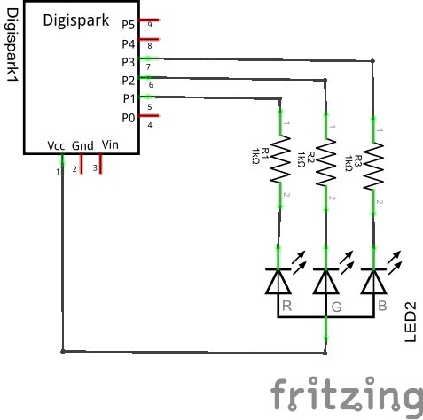
#Fritzing rgb led driver
The led strip driver combines 4 parts, each with their own complications and limitations. Problems, complications and stuff to fix later. The competing chip, the WS2801, has 8 bits PWM resolution and may suffer less from posterising, That explains the posterising you can see in movies below. So for indoor use I’m using it at about 10%, effectively killing off 3 of the 7 bits.
#Fritzing rgb led full
The problem is that the LED strips are pretty bright, when the the LED are driven full brightness my eyes and the camera are pretty much blinded. The LPD8806 have 7 bits of PWM resolution allowing for 2 21 (about 2 million) colors. USB hubs and main board chipsets can cause additional artifacts. The pauses between the USB frames are caused by the combination of the Teensy USB, the OS USB stack and the Processing application. One image in the LED stripĪbove is one complete LED strip image, the last block (right) only contains o’s and latches the pattern in the strip. You can just see the “H”, “E” and “L” in the pattern driving the LED strips. A complete image of 13 (64 byte) usb frames takes about 1 ms. (1.16 MHz), One 64 byte frame takes 56 us. The byte clock in a frame is about 800 ns. Notes: 2 The first USB frame of the image, the lower line is the clock line. There are 64 bytes in this frame, driving a little more than 2 columns with 8 leds each.

The time the teensy needs for pushing out one USB frame is 58 us. The only challenge now was to hook it all up and write a example program that creates an image and serializes it to the teensy.īelow is an image of the first USB frame in the led strip image.
#Fritzing rgb led code
Paul’s code worked right away (a classic example of loop unrolling, trading code size for execution speed). This reduces the number of boards per strand. One of the 8 bit ports is used to drive the data pin on 8 led strips, one pin on one other port is used to drive all clock pins. In this solution a Teensy is used to drive 8 strips simultaneously.


Paul Stoffregen’s (of Teensy fame) post on the teensy as a USB byte pump ( and ) showed me the right direction. The last problem is that the Arduino is too small and slow to handle large bitmaps by itself and a bit cumbersome as an IO extender. The other is that if you want to run strips in parallel you’ll need one Arduino per strand. One is that all the power for all strips (1 Ampere per meter or more) will flow through the first strip. You can scale this solution by daisy chaining strips but there are come complications with this approach. The chip could use a blog post on it’s own.Īdafruit have some excellent examples driving one led strip with the arduino SPI. One (or more) zero bytes latch the pattern in the strip, eliminating the need to constantly refresh the strip. 1 meter of these strips has 32 LED’s and 16 chips, forming a 384 byte long shift register. On the other side the chips shift out the bits 6 bytes delayed. The chips shift in 1 byte per led color (3 per led module) and use 7 bits of the byte to drive the intensity of the LED via PWM. Red Green Blue, Light Emitting Diode, per pixel controllable strips.Īdafruit and various other vendors sell RGB LED strips with one LPD8806 chip per 2 RGB LED modules.


 0 kommentar(er)
